
Tuesday 29 July 2008
Monday 28 July 2008
Yoke Fitting
Well tonight it was time to re-cable the sim. Its now all neat and routed better to support the panel being in front of the screen. The wires now all route down the side of the table so as not to get caught under the panel which rests on the desk when in use.
I also took the chance to get around the stupid mount on the CH Yoke that meant it never fitted on the desk properly. The issue is it wont clamp to a desk under about 2cm thick. Sadly my chipboard desk is 1cm thick...
My solution was to screw a strip of wood to the edge of the desk underneath, now for the first time the yoke is firmly fitted. Although I now can more easily skim my knees on the desk ;)
Tuesday 22 July 2008
Panel Solution


Well I got the panel working, the issue was stupidly simple. I built the panel at 1280 x 1024, and FSX was set to run in 1024 x 768... doh.
Once that was sorted I was able to start pulling the instruments together. Still needs tweaking, but it is already flyable. Thank goodness, with access to instruments and the ability to look around I actually landed ok. Yesterday without the panel flying VC only my visual approach was awful!
Monday 21 July 2008
Mockup Panel
 I have fitted the GoFlight modules and the Hobbs meter, really feels like it is getting somewhere now. For the picture I mocked up the instruments, but in reality they are driving me mad.
Every time I set it all up it looks great. But put it in FSX, top screen is fine, bottom screen it all gets larger.... GRRRR...
Both screens are the same resolution, at least outside of FSX. I will need to either trial end error it, or spend some time online in the newsgroups working out what I am doing wrong. Most likely I will need to do both.
Still its feels good to have it starting to look right, despite the setbacks.
Sunday 20 July 2008
GoFlight Test
 I finally got to digging out my GoFlight modules, a GF-45 and RP48 brought a few years back on ebay. They took a little coaxing, but I got them running in FSX. Still seem to be having some issues with the RP48 and my RealityXP guages, but its getting there. In the final design I wont be using the goflight modules to control the altimeter or heading bug, I hope to use the rotary encoders installed directly in the panel through Leo's joystick interface.
That will leave me 4 encoders for use with goflight. I think they will end up being used for dimmer, selecting the mode on the GF-45, and rudder / elevator trims.
Next step is to panel mount them in my new cockpit panel. The RP48 will go at the top of my stack, the 8 buttons neatly line up with the audio 8 buttons in the aircraft normally mounted at the top, So that is likely to be their use. The lights, cowl heat, etc will go through my still to be purchased joystick interface.
The picture shows the test run, I still need to build a new panel in FSX to run on the lower monitor through the wood template. So while flying I am still running 1 screen with virtual cockpit hence the upper screen being dark.
Saturday 12 July 2008
Hold for incoming traffic
Ok, no progress for 3 months... well we had a new landing in the family and she has taken most of that thing we call 'Free Time':

Still the bug is catching me up, last night saw a gentle flight from Fairoaks to Sandown at dusk. See below for the screenshot, pure joy to complete.
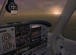
(we wont mention me bending the prop on the landing... long time no fly. Lack of sleep, and rushing the approach is just as bad in a virtual world as in the real one. Luckily there is no AAIB in FSX)
Monday 28 April 2008
Holy Cockpit Batman


Well I now have a holesaw the size I wanted, 80mm. So I have drilled out the instrument holes and also the keyswitch. However the instruments are too close to the edge of the panel. I correctly allowed for the visible screen area in my design. What I forgot was the angle you view them at! Viewing at any angle you can see the edges of the screen :(
So I have decided that I will complete this panel and all the back end framework as a learning exercise. Then replace the front plate with a new one incorporating all I learned from building it the first time. Luckily I brought more than 1 piece, I have 3 identical bits of MDF so this wont be too hard.
As shown in the last pic, part of the frame is started. Its a table from Ikea that is just the right size, well almost, and solid pine :)
Tuesday 22 April 2008

I now have the rotary encoders off ebay to setup the intrument controls. Shown on the right, on top of the white square. The knobs are too large, but first problem is working out how to fit the encoders.
My little box of bits for the panel is growing nicely now. I only need one of the 2 guarded and iluminated switches shown on the orange network lead. However I think I will use the other one as a PC power switch.
Also shown are my 2 go flight modules, and the hobbs meter, to the left of the switches which is also courtesy of ebay.
Friday 18 April 2008
Blasted colds.. and 80mm saws...
Well as the title suggests I am suffering from the dreaded lurgy, or common cold. Also hit a brick wall when it came to buying an 80mm hole saw for the instrument cutouts. Off at the weekend to a larger supplier to source one.
Monday 14 April 2008
Start of Panel Markout

Finally got over enough of my cold to start marking out the plan on the wood. So far I have done the main instruments, the left hand headset hookups, start switch location, and ELT switch. Still to go is the avionics bay, clock and suction, and fuseboard locations.
Finally I will need to draw the top edge, then cut to shape.
Saturday 12 April 2008
First hardware

Purchased some 3mm mdf, £5.50 including cutting to 102 x 48 cm which is rough outer dimensions for my panel. Also grabbed some planed wood for the frame to hold it and 90 degree metal corners to help build it up.
Total cost so far just under £20.
I also put the order in last week for the rotary encoders off ebay. Sold by http://stores.ebay.co.uk/Sure-Electronics
These were suggested by some of the peeps at MyCockpit.org as being compatible with the card from Leo Bodnar. I plan to try and use them to drive the altimeter and nav instruments.
Wednesday 9 April 2008
The Plan

To the right is my initial design plan, using a document based on the cockpit dimensions I then expanded a copy of a stock photo to match. Very easy to do, and I hope quite accurate using the freeware OpenOffice.org 'Draw' program. The scales down the sides are in CM.
With semi-transparent overlays I then worked out where I could put my monitor behind the panel. Now trying to work out what to put behind this to hold up the panel once made.
I want to use a joystick interface card to handle the switches, and also re-use my desktop aviator panel. With the support for rotary encoders I hope to mount mini rotary encoders on the surface of the panel to make working instrument knobs. Cables will run behind the panel and sticky back felt on the back of the board should hide them and protect the screen. Panel will be made of 2mm thick MDF.
Once I have the panel complete as a desktop version, I plan to build an enclosure in 2 parts (nose to panel / seating and sides) to house it. Hopefully it will fit through the doorways if we move. The lower picture shows the plan for a shelf at the bottom of the panel which will hold a joystick on the right, and the yoke on the left.
 I am thinking of getting a Saitek throttle quad as this will not only neatly handle the single engine planes I fly, but also the complex SF-260 I relax in. Finally there will be a very small keyboard, already purchased from Maplin as I only have 1 PC and need a way to type updates like this.
I still need to workout how to do the annunciators which overlap the monitor edge so cant go through the panel. Radios / transponder will be handled by my go flight modules so should be no major issue.
Also I am still hunting around for some large white piper style switches, not found any as yet.
Unlike my current cockpit I am not going to use a poster, and I am going from scratch in the panel design. So now there are 3 main steps to get sorted:
1. A desktop version which sits on my existing desk but is 1:1 scale, and includes all my 'toys'.
2. A replacement for my desk which will hold the desktop panel, and provide space for the PC and pedals. Closed in to protect from house rabbits...
3. Sides for the seating area, also mounted on a base which will connect to the 'nose' and give a complete cockpit.
Now to get back to bits of paper, and work out how to make the 'desktop' part of this.
Current Cockpit April 2008

Ok, where to start. I suppose we should begin with my current cockpit shown left. This uses a 17in TFT to provide instruments and a 19in CRT for the outside world.
Switches on the right are linked via a joystick interface to the flight simulator. They control the lights, and engine startup.
Start of an idea
Well I have got pen, paper, and photos to hand... now to start writing down my plans in a blog so I can look back in years to come and say "wow, 3 years and I still not got anywhere." ;)

Subscribe to:
Posts (Atom)